Skip to content

The graphics modes

Text mode is one of four things the video card can do. The other three draw pixels, and getting into them means setting the card's eight mode registers yourself — the Kernal has no calls for it, because there is no one right way to lay out a screen.

All three are 256 × 192 pixels. What differs is how much color you can afford and how much memory it costs.

ModeCellsWhat you get
Graphics I32 × 24 of 8 × 8256 patterns, and one color pair per group of eight patterns
Graphics II32 × 24 of 8 × 8Every cell its own pattern, and a color pair for every pixel row
Multicolor64 × 48 blocks of 4 × 4Straight color, no patterns to think about, chunky pixels

Sprites work in all three: 32 of them, 8 × 8 or 16 × 16, one color each, moved by writing a coordinate.

Getting into one

The recipe is the same every time:

  1. Blank the display by clearing bit 6 of register 1. Nothing on screen while you load, so nothing flickers.
  2. Write the eight mode registers — screen mode, and where in the card's 16 KB each table lives.
  3. Fill the tables: patterns, colors, names, and a sprite list that is at least terminated.
  4. Un-blank.

And to get out again, InitVideo followed by VideoClear puts text mode and the character set back exactly as they were.

Interrupts and the card do not mix

Every register write is a pair of bytes to the same address. An interrupt in between, whose handler also talks to the card, leaves both of you out of step. The demos below sei before touching the registers and cli afterwards — and they have to cli again before waiting for a key, because keys arrive by interrupt.

Graphics I

The plain one. 256 patterns of 8 × 8, and a 32-byte color table: one entry per eight patterns, foreground in the high nibble, background in the low. That is exactly 32 color combinations on screen, which this demo shows off by giving every pattern the same checkerboard and letting only the color vary.

asm
.setcpu "65C02"

.include "6502.inc"

.segment "CODE"

; =============================================================================
;   BASIC Startup Stub
; =============================================================================
;   A tokenized BASIC line: 10 SYS 2060
;   When this program is loaded into $0800 and RUN in BASIC, the SYS command
;   jumps to the machine code entry point at $080C (decimal 2060).
;   This stub must remain at the very start of the program.

BasicStartup: .byte $0A, $08, $0A, $00, $A5, $32, $30, $36, $30, $00, $00, $00

; =============================================================================
;   TMS9918 Graphics Mode I Demo ($080C)
; =============================================================================
;   Builds a character set of 256 identical checkerboard patterns, gives the
;   color table 32 different foreground/background pairs, and fills the
;   screen with random characters.  Waits for a key press, restores text mode,
;   and returns to BASIC.
;
;   GRAPHICS MODE I
;   ---------------
;   Selected by M1=0, M2=0, M3=0 (the plain graphics mode).  The screen is
;   32 x 24 cells of 8 x 8 pixels.  Each name table entry selects one of 256
;   patterns from the 2 KB pattern table.
;
;   Color is coarse: the 32-byte color table holds one entry per *group of
;   eight* patterns (high nibble = foreground, low nibble = background), so
;   characters $00-$07 share entry 0, $08-$0F share entry 1, and so on.
;   That gives exactly 32 color combinations per screen — which is what this
;   demo shows off.  Since every pattern is the same checkerboard, the only
;   thing that varies across the screen is the color pair.
; =============================================================================

; --- Zero page (safe user range is $3A-$FF) ---
RND             = $3A               ; 2 bytes — PRNG state (must never be $0000)

; --- Screen geometry (the graphics modes are 32 columns wide, not 40) ---
GFX_COLS        = 32
GFX_ROWS        = VID_ROWS
GFX_CELLS       = GFX_COLS * GFX_ROWS   ; 768 name table entries

; --- VRAM layout ---
G1_NAME         = $0000             ; Name table         ($0000-$02FF, 768 bytes)
G1_COLOR        = $0300             ; Color table       ($0300-$031F, 32 bytes)
G1_SPR_ATTR     = $0700             ; Sprite attributes  ($0700-$077F)
G1_PATTERN      = $0800             ; Pattern table      ($0800-$0FFF, 2048 bytes)

; --- Register 1 values (16K VRAM, VDP interrupt off, Graphics mode) ---
R1_BLANK        = %10000000         ; Display blanked — used while loading VRAM
R1_ACTIVE       = %11000000         ; Display enabled

RND_SEED        = $C33C             ; Fixed seed: the same screen every run

; =============================================================================
;   Start — Program entry point
; =============================================================================

Start:
  lda HW_PRESENT
  and #HW_VID                       ; Is a video card present?
  bne @HaveVideo
  lda #<NoVideoMsg
  ldy #>NoVideoMsg
  jsr PrintStr
  jsr PrintCRLF
  rts                               ; Nothing to demo — back to BASIC

@HaveVideo:
  sei                               ; The Kernal IRQ handler must not touch the
                                    ; VDP between our two-byte port writes
  jsr InitRandom
  jsr InitMode                      ; Mode registers, display still blanked
  jsr HideSprites
  jsr FillPatterns                  ; 256 copies of the checkerboard
  jsr FillColors                    ; 32 foreground/background pairs
  jsr FillNames                     ; Random character in every cell
  jsr ShowDisplay
  cli

  jsr WaitKey                       ; Needs interrupts — input is IRQ driven

  sei
  jsr InitVideo                     ; Restore the BIOS text mode
  jsr VideoClear
  cli

End:
  rts                               ; Return to BASIC

; =============================================================================
;   InitMode — Load the VDP registers for Graphics Mode I
; =============================================================================

InitMode:
  lda VC_STATUS                     ; Reset the VDP address/data flip-flop
  ldx #0
@Loop:
  lda VdpRegs,x
  sta VC_REG                        ; Data byte first...
  txa
  ora #$80                          ; ...then register number | $80
  sta VC_REG
  inx
  cpx #8
  bne @Loop
  rts

; =============================================================================
;   ShowDisplay — Un-blank the display now that VRAM is loaded
; =============================================================================

ShowDisplay:
  lda #R1_ACTIVE
  ldx #1
  jmp SetVdpReg

; =============================================================================
;   HideSprites — Terminate the sprite list so no sprites are drawn
; =============================================================================

HideSprites:
  lda #<G1_SPR_ATTR
  ldx #>G1_SPR_ATTR
  jsr SetVramWrite
  lda #$D0                          ; Y = $D0 ends the sprite list
  sta VC_DATA
  rts

; =============================================================================
;   FillPatterns — Give all 256 characters the same checkerboard pattern
; =============================================================================
;   256 patterns x 8 bytes = 2048 bytes.

FillPatterns:
  lda #<G1_PATTERN
  ldx #>G1_PATTERN
  jsr SetVramWrite
  ldy #0                            ; 256 patterns (Y wraps to 0)
@Pattern:
  ldx #0
@Row:
  lda Checker,x
  sta VC_DATA
  inx
  cpx #8
  bne @Row
  dey
  bne @Pattern
  rts

; =============================================================================
;   FillColors — One foreground/background pair per group of 8 characters
; =============================================================================

FillColors:
  lda #<G1_COLOR
  ldx #>G1_COLOR
  jsr SetVramWrite
  ldx #0
@Loop:
  lda Colors,x
  sta VC_DATA
  inx
  cpx #32
  bne @Loop
  rts

; =============================================================================
;   FillNames — Put a random character in every screen cell
; =============================================================================
;   768 bytes = 3 x 256.  A random character code picks a random color group.

FillNames:
  lda #<G1_NAME
  ldx #>G1_NAME
  jsr SetVramWrite
  ldx #GFX_CELLS / 256              ; 3 blocks of 256 bytes
@Block:
  ldy #0
@Byte:
  jsr Random
  sta VC_DATA
  iny
  bne @Byte
  dex
  bne @Block
  rts

; =============================================================================
;   VDP Helpers
; =============================================================================

; SetVdpReg — write a VDP register
;   In: A = value, X = register number (0-7)
SetVdpReg:
  sta VC_REG
  txa
  ora #$80
  sta VC_REG
  rts

; SetVramWrite — set the VRAM address for auto-incrementing writes
;   In: A = address low byte, X = address high byte
SetVramWrite:
  sta VC_REG
  txa
  ora #$40                          ; $40 flags a write
  sta VC_REG
  rts

; =============================================================================
;   Random — 16-bit xorshift PRNG
; =============================================================================
;   Out: A = pseudo-random byte.  Preserves X and Y.

InitRandom:
  lda #<RND_SEED
  sta RND
  lda #>RND_SEED
  sta RND+1
  rts

Random:
  lda RND+1
  lsr a
  lda RND
  ror a
  eor RND+1
  sta RND+1
  ror a
  eor RND
  sta RND
  eor RND+1
  sta RND+1
  rts

; =============================================================================
;   WaitKey — Discard pending input, then block until a key is pressed
; =============================================================================

WaitKey:
  jsr BufferSize                    ; A = unread bytes in the input buffer
  cmp #0
  beq @Wait
  jsr ReadBuffer                    ; Drain stale input (no echo)
  bra WaitKey
@Wait:
  jsr BufferSize
  cmp #0
  beq @Wait
  jsr ReadBuffer
  rts

; =============================================================================
;   Data
; =============================================================================

; VDP registers 0-7
VdpRegs:
  .byte $00                         ; R0: M3=0, no external video
  .byte R1_BLANK                    ; R1: 16K, blanked, Graphics Mode I
  .byte $00                         ; R2: name table         @ $0000
  .byte $0C                         ; R3: color table       @ $0300
  .byte $01                         ; R4: pattern table      @ $0800
  .byte $0E                         ; R5: sprite attributes  @ $0700
  .byte $01                         ; R6: sprite patterns    @ $0800
  .byte TMS_BLACK                   ; R7: backdrop color

; The one and only character: a single-pixel checkerboard filling the 8x8 cell,
; so every cell reads as one textured tile in its own two colors.
;
; The 1x1 grain matters — Multicolor mode cannot draw anything finer than a 4x4
; block, so resolving this texture at all confirms the VDP really is in Graphics
; Mode I and not falling back to Multicolor.
Checker:
  .byte %01010101
  .byte %10101010
  .byte %01010101
  .byte %10101010
  .byte %01010101
  .byte %10101010
  .byte %01010101
  .byte %10101010

; 32 color table entries — (foreground << 4) | background.
; Entry n colors characters (n * 8) through (n * 8 + 7).
Colors:
  .byte (TMS_WHITE     << 4) | TMS_BLACK        ; chars $00-$07
  .byte (TMS_BLACK     << 4) | TMS_WHITE        ; chars $08-$0F
  .byte (TMS_MED_GREEN << 4) | TMS_BLACK        ; chars $10-$17
  .byte (TMS_BLACK     << 4) | TMS_MED_GREEN    ; chars $18-$1F
  .byte (TMS_LT_GREEN  << 4) | TMS_DK_GREEN
  .byte (TMS_DK_GREEN  << 4) | TMS_LT_GREEN
  .byte (TMS_DK_BLUE   << 4) | TMS_LT_BLUE
  .byte (TMS_LT_BLUE   << 4) | TMS_DK_BLUE
  .byte (TMS_DK_RED    << 4) | TMS_LT_RED
  .byte (TMS_LT_RED    << 4) | TMS_DK_RED
  .byte (TMS_CYAN      << 4) | TMS_DK_BLUE
  .byte (TMS_DK_BLUE   << 4) | TMS_CYAN
  .byte (TMS_MED_RED   << 4) | TMS_LT_YELLOW
  .byte (TMS_LT_YELLOW << 4) | TMS_MED_RED
  .byte (TMS_DK_YELLOW << 4) | TMS_DK_GREEN
  .byte (TMS_DK_GREEN  << 4) | TMS_DK_YELLOW
  .byte (TMS_MAGENTA   << 4) | TMS_GRAY
  .byte (TMS_GRAY      << 4) | TMS_MAGENTA
  .byte (TMS_WHITE     << 4) | TMS_DK_BLUE
  .byte (TMS_DK_BLUE   << 4) | TMS_WHITE
  .byte (TMS_LT_GREEN  << 4) | TMS_BLACK
  .byte (TMS_BLACK     << 4) | TMS_LT_GREEN
  .byte (TMS_CYAN      << 4) | TMS_MAGENTA
  .byte (TMS_MAGENTA   << 4) | TMS_CYAN
  .byte (TMS_LT_YELLOW << 4) | TMS_DK_RED
  .byte (TMS_DK_RED    << 4) | TMS_LT_YELLOW
  .byte (TMS_GRAY      << 4) | TMS_BLACK
  .byte (TMS_BLACK     << 4) | TMS_GRAY
  .byte (TMS_LT_RED    << 4) | TMS_DK_GREEN
  .byte (TMS_DK_GREEN  << 4) | TMS_LT_RED
  .byte (TMS_WHITE     << 4) | TMS_MED_RED
  .byte (TMS_MED_RED   << 4) | TMS_WHITE        ; chars $F8-$FF

NoVideoMsg: .asciiz "No video card present."
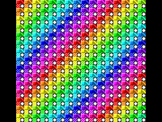
A screen filled with a grid of checkered cells in many different two-color combinations.
Every cell is the same checkerboard pattern. All that varies is the color pair — thirty-two of them, which is the whole of what this mode gives you.

Worth noticing in that listing:

  • InitMode writes the eight registers from a table. The values are the whole of "which mode is this" — there is no mode number.
  • HideSprites writes $D0 as the first sprite's vertical position, which is the card's way of saying "the sprite list ends here". Skip it and you get whatever was in memory, drawn as sprites.
  • The random number generator is a sixteen-bit shift-and-xor, seeded with a constant so the screen comes out the same every run. Seed it from the clock instead and it never does.
  • SetVramWrite and SetVdpReg are four instructions each and get used everywhere. They are worth copying into anything you write.

Graphics II

The same shape with the tables grown to 6144 bytes each, split into three horizontal thirds of eight rows, each third indexing its own 2 KB slice. Every one of the 768 cells can have its own pattern and a color pair per pixel row, which is what makes proper pictures possible.

The catch is in registers 3 and 4: in this mode their low bits are an AND mask over the table rather than more address, so they have to be all ones — $FF and $03 — to expose the full 6144 bytes. Getting that wrong is the classic Graphics II bug, and the symptom is a screen that repeats every third.

The full listing
asm
.setcpu "65C02"

.include "6502.inc"

.segment "CODE"

; =============================================================================
;   BASIC Startup Stub
; =============================================================================
;   A tokenized BASIC line: 10 SYS 2060
;   When this program is loaded into $0800 and RUN in BASIC, the SYS command
;   jumps to the machine code entry point at $080C (decimal 2060).
;   This stub must remain at the very start of the program.

BasicStartup: .byte $0A, $08, $0A, $00, $A5, $32, $30, $36, $30, $00, $00, $00

; =============================================================================
;   TMS9918 Graphics Mode II Demo ($080C)
; =============================================================================
;   Same idea as the Graphics Mode I demo, but with per-row color: every cell
;   on screen gets its own checkerboard pattern *and* its own eight random
;   color pairs, one per pixel row.  Waits for a key press, restores text
;   mode, and returns to BASIC.
;
;   GRAPHICS MODE II
;   ----------------
;   Selected by M3=1 (R0 bit 1 set).  Still 32 x 24 cells of 8 x 8 pixels, but
;   the pattern and color tables grow to 6144 bytes each and the screen is
;   split into three horizontal thirds of 8 rows.  Each third indexes its own
;   2 KB slice of those tables, so all 768 cells can have unique pixels and
;   unique color — 256 KB worth of freedom compared to Mode I's 256 patterns.
;
;   The color table is the important part: it is the same shape as the
;   pattern table, one byte per pattern byte, so *every pixel row* of every
;   cell carries its own foreground/background pair (high nibble / low
;   nibble).  This demo fills all 6144 color bytes with random pairs.
;
;   VRAM layout (the usual Graphics II arrangement):
;     $0000-$17FF   Pattern table    (6144 bytes)   R4 = $03
;     $1800-$1AFF   Name table       (768 bytes)    R2 = $06
;     $1B00-$1B7F   Sprite attrs                    R5 = $36
;     $2000-$37FF   Color table     (6144 bytes)   R3 = $FF
;     $3800-$3FFF   Sprite patterns                 R6 = $07
;
;   Note R3 and R4 are interpreted differently in this mode: only their top
;   address bit selects the base ($0000 or $2000) and the remaining low bits
;   are an AND mask over the table, which must be all ones to expose the full
;   6144 bytes.  Hence R3 = $FF and R4 = $03 rather than plain multiples.
; =============================================================================

; --- Zero page (safe user range is $3A-$FF) ---
RND             = $3A               ; 2 bytes — PRNG state (must never be $0000)
TMP             = $3C               ; 1 byte  — scratch
FG              = $3D               ; 1 byte  — foreground nibble being built
BLOCKS          = $3E               ; 1 byte  — outer loop counter

; --- Screen geometry (the graphics modes are 32 columns wide, not 40) ---
GFX_COLS        = 32
GFX_ROWS        = VID_ROWS
GFX_CELLS       = GFX_COLS * GFX_ROWS   ; 768 name table entries

; --- VRAM layout ---
G2_PATTERN      = $0000             ; Pattern table      ($0000-$17FF, 6144 bytes)
G2_NAME         = $1800             ; Name table         ($1800-$1AFF, 768 bytes)
G2_SPR_ATTR     = $1B00             ; Sprite attributes  ($1B00-$1B7F)
G2_COLOR        = $2000             ; Color table       ($2000-$37FF, 6144 bytes)

; --- Register 1 values (16K VRAM, VDP interrupt off) ---
R1_BLANK        = %10000000         ; Display blanked — used while loading VRAM
R1_ACTIVE       = %11000000         ; Display enabled

RND_SEED        = $1234             ; Fixed seed: the same screen every run

; =============================================================================
;   Start — Program entry point
; =============================================================================

Start:
  lda HW_PRESENT
  and #HW_VID                       ; Is a video card present?
  bne @HaveVideo
  lda #<NoVideoMsg
  ldy #>NoVideoMsg
  jsr PrintStr
  jsr PrintCRLF
  rts                               ; Nothing to demo — back to BASIC

@HaveVideo:
  sei                               ; The Kernal IRQ handler must not touch the
                                    ; VDP between our two-byte port writes
  jsr InitRandom
  jsr InitMode                      ; Mode registers, display still blanked
  jsr HideSprites
  jsr FillPatterns                  ; 768 checkerboards, one per cell
  jsr FillColors                    ; A random color pair per pixel row
  jsr FillNames                     ; $00-$FF in each third of the screen
  jsr ShowDisplay
  cli

  jsr WaitKey                       ; Needs interrupts — input is IRQ driven

  sei
  jsr InitVideo                     ; Restore the BIOS text mode
  jsr VideoClear
  cli

End:
  rts                               ; Return to BASIC

; =============================================================================
;   InitMode — Load the VDP registers for Graphics Mode II
; =============================================================================

InitMode:
  lda VC_STATUS                     ; Reset the VDP address/data flip-flop
  ldx #0
@Loop:
  lda VdpRegs,x
  sta VC_REG                        ; Data byte first...
  txa
  ora #$80                          ; ...then register number | $80
  sta VC_REG
  inx
  cpx #8
  bne @Loop
  rts

; =============================================================================
;   ShowDisplay — Un-blank the display now that VRAM is loaded
; =============================================================================

ShowDisplay:
  lda #R1_ACTIVE
  ldx #1
  jmp SetVdpReg

; =============================================================================
;   HideSprites — Terminate the sprite list so no sprites are drawn
; =============================================================================

HideSprites:
  lda #<G2_SPR_ATTR
  ldx #>G2_SPR_ATTR
  jsr SetVramWrite
  lda #$D0                          ; Y = $D0 ends the sprite list
  sta VC_DATA
  rts

; =============================================================================
;   FillPatterns — The same checkerboard in all 768 pattern slots
; =============================================================================
;   6144 bytes = 3 x 256 patterns x 8 bytes.

FillPatterns:
  lda #<G2_PATTERN
  ldx #>G2_PATTERN
  jsr SetVramWrite
  lda #GFX_CELLS / 256              ; 3 thirds of 256 patterns
  sta BLOCKS
@Block:
  ldy #0                            ; 256 patterns (Y wraps to 0)
@Pattern:
  ldx #0
@Row:
  lda Checker,x
  sta VC_DATA
  inx
  cpx #8
  bne @Row
  dey
  bne @Pattern
  dec BLOCKS
  bne @Block
  rts

; =============================================================================
;   FillColors — A random foreground/background pair for every pixel row
; =============================================================================
;   6144 bytes = 24 x 256.  This is what Mode II buys you over Mode I: eight
;   independent color pairs per cell instead of one per eight characters.

FillColors:
  lda #<G2_COLOR
  ldx #>G2_COLOR
  jsr SetVramWrite
  ldx #24                           ; 24 blocks of 256 bytes
@Block:
  ldy #0
@Byte:
  jsr RandomColor
  sta VC_DATA
  iny
  bne @Byte
  dex
  bne @Block
  rts

; =============================================================================
;   FillNames — Point each third of the screen at its own table slice
; =============================================================================
;   768 bytes = $00-$FF repeated three times, so every cell has a unique
;   pattern/color slot.

FillNames:
  lda #<G2_NAME
  ldx #>G2_NAME
  jsr SetVramWrite
  ldx #GFX_CELLS / 256              ; 3 thirds of 256 cells
@Block:
  ldy #0
@Byte:
  tya
  sta VC_DATA
  iny
  bne @Byte
  dex
  bne @Block
  rts

; =============================================================================
;   RandomColor — Build a color byte whose two nibbles always differ
; =============================================================================
;   Out: A = (foreground << 4) | background, foreground != background.
;   Preserves X and Y.
;
;   The background is derived as foreground XOR a non-zero delta, which
;   guarantees the two nibbles never match and so the checkerboard is always
;   visible.  Color 0 is transparent and shows the backdrop, which is black
;   here, so it simply reads as black.

RandomColor:
  jsr Random
  sta TMP
  and #$0F
  sta FG                            ; Foreground = low nibble (0-15)
  lda TMP
  lsr a
  lsr a
  lsr a
  lsr a                             ; High nibble becomes the XOR delta
  bne @Delta
  lda #$01                          ; A zero delta would leave background = foreground
@Delta:
  eor FG                            ; Background = foreground XOR delta
  sta TMP
  lda FG
  asl a
  asl a
  asl a
  asl a
  ora TMP
  rts

; =============================================================================
;   VDP Helpers
; =============================================================================

; SetVdpReg — write a VDP register
;   In: A = value, X = register number (0-7)
SetVdpReg:
  sta VC_REG
  txa
  ora #$80
  sta VC_REG
  rts

; SetVramWrite — set the VRAM address for auto-incrementing writes
;   In: A = address low byte, X = address high byte
SetVramWrite:
  sta VC_REG
  txa
  ora #$40                          ; $40 flags a write
  sta VC_REG
  rts

; =============================================================================
;   Random — 16-bit xorshift PRNG
; =============================================================================
;   Out: A = pseudo-random byte.  Preserves X and Y.

InitRandom:
  lda #<RND_SEED
  sta RND
  lda #>RND_SEED
  sta RND+1
  rts

Random:
  lda RND+1
  lsr a
  lda RND
  ror a
  eor RND+1
  sta RND+1
  ror a
  eor RND
  sta RND
  eor RND+1
  sta RND+1
  rts

; =============================================================================
;   WaitKey — Discard pending input, then block until a key is pressed
; =============================================================================

WaitKey:
  jsr BufferSize                    ; A = unread bytes in the input buffer
  cmp #0
  beq @Wait
  jsr ReadBuffer                    ; Drain stale input (no echo)
  bra WaitKey
@Wait:
  jsr BufferSize
  cmp #0
  beq @Wait
  jsr ReadBuffer
  rts

; =============================================================================
;   Data
; =============================================================================

; VDP registers 0-7
VdpRegs:
  .byte $02                         ; R0: M3=1 (Graphics Mode II)
  .byte R1_BLANK                    ; R1: 16K, blanked
  .byte $06                         ; R2: name table         @ $1800
  .byte $FF                         ; R3: color table       @ $2000, full mask
  .byte $03                         ; R4: pattern table      @ $0000, full mask
  .byte $36                         ; R5: sprite attributes  @ $1B00
  .byte $07                         ; R6: sprite patterns    @ $3800
  .byte TMS_BLACK                   ; R7: backdrop color

; Every pattern is the same single-pixel checkerboard used by the Graphics Mode I
; demo, which makes the two directly comparable: identical tile, but here each
; of its eight pixel rows carries its own color pair instead of the whole cell
; sharing one.  Both row values have four set and four clear bits, so every row
; shows both of its colors.
Checker:
  .byte %01010101
  .byte %10101010
  .byte %01010101
  .byte %10101010
  .byte %01010101
  .byte %10101010
  .byte %01010101
  .byte %10101010

NoVideoMsg: .asciiz "No video card present."
A screen densely filled with small colored checkered blocks, finer and more varied than the Graphics I screen.
Graphics II, filled with random patterns. Each cell has its own pattern and its own color for every pixel row, which is what makes a real picture possible.

Multicolor

No patterns and no color table: the pattern table is the picture, one nibble per 4 × 4 block. 64 × 48 blocks, sixteen colors, and you paint by writing bytes.

There is one trick to it. Each name-table cell covers 2 × 2 blocks and so uses only two of its pattern's eight bytes — which two depends on the cell's row within a group of four. Give all four rows of a group the same name and one eight-byte pattern covers the lot, at which point the pattern table becomes a plain 1536-byte framebuffer that you can fill from top to bottom.

The full listing
asm
.setcpu "65C02"

.include "6502.inc"

.segment "CODE"

; =============================================================================
;   BASIC Startup Stub
; =============================================================================
;   A tokenized BASIC line: 10 SYS 2060
;   When this program is loaded into $0800 and RUN in BASIC, the SYS command
;   jumps to the machine code entry point at $080C (decimal 2060).
;   This stub must remain at the very start of the program.

BasicStartup: .byte $0A, $08, $0A, $00, $A5, $32, $30, $36, $30, $00, $00, $00

; =============================================================================
;   TMS9918 Multicolor Mode Demo ($080C)
; =============================================================================
;   Fills the screen with randomly colored 4x4 pixel blocks, then waits for
;   a key press, restores text mode, and returns to BASIC.
;
;   MULTICOLOR MODE
;   ---------------
;   Selected by M1=0, M2=1, M3=0 (R1 bit 3 set).  The display is 64 x 48
;   blocks of 4 x 4 pixels.  There is no color table — color comes straight
;   out of the pattern table, one nibble per block (high nibble = left block,
;   low nibble = right block).
;
;   Each of the 32 x 24 name table cells covers 8 x 8 pixels = 2 x 2 blocks,
;   so it consumes only 2 of the 8 bytes of its pattern.  Which pair is used
;   depends on the cell's row: rows 0,4,8..  use bytes 0-1, rows 1,5,9.. use
;   bytes 2-3, rows 2,6,10.. use bytes 4-5, rows 3,7,11.. use bytes 6-7.
;
;   Giving the four rows of each row-group the *same* name therefore lets one
;   8-byte pattern cover all four, and the pattern table becomes a plain
;   linear framebuffer:
;
;     name[row][col] = (row / 4) * 32 + col        -> 192 patterns
;     192 patterns x 8 bytes                       -> 1536 bytes = 64 x 48
;
;   So filling the pattern table with random bytes paints the whole screen.
; =============================================================================

; --- Zero page (safe user range is $3A-$FF) ---
RND             = $3A               ; 2 bytes — PRNG state (must never be $0000)
ROW_BASE        = $3C               ; 1 byte  — name table base for current row

; --- VRAM layout ---
MC_NAME         = $0000             ; Name table          ($0000-$02FF, 768 bytes)
MC_SPR_ATTR     = $0700             ; Sprite attributes   ($0700-$077F)
MC_PATTERN      = $0800             ; Pattern table       ($0800-$0DFF, 1536 bytes)

; --- Screen geometry (the graphics modes are 32 columns wide, not 40) ---
GFX_COLS        = 32
GFX_ROWS        = VID_ROWS

; --- Register 1 values (16K VRAM, VDP interrupt off, Multicolor mode) ---
R1_BLANK        = %10001000         ; Display blanked — used while loading VRAM
R1_ACTIVE       = %11001000         ; Display enabled

RND_SEED        = $A55A             ; Fixed seed: the same screen every run

; =============================================================================
;   Start — Program entry point
; =============================================================================

Start:
  lda HW_PRESENT
  and #HW_VID                       ; Is a video card present?
  bne @HaveVideo
  lda #<NoVideoMsg
  ldy #>NoVideoMsg
  jsr PrintStr
  jsr PrintCRLF
  rts                               ; Nothing to demo — back to BASIC

@HaveVideo:
  sei                               ; The Kernal IRQ handler must not touch the
                                    ; VDP between our two-byte port writes
  jsr InitRandom
  jsr InitMode                      ; Mode registers, display still blanked
  jsr HideSprites
  jsr FillNames                     ; Name table -> linear framebuffer layout
  jsr FillPatterns                  ; Pattern table -> random block colors
  jsr ShowDisplay
  cli

  jsr WaitKey                       ; Needs interrupts — input is IRQ driven

  sei
  jsr InitVideo                     ; Restore the BIOS text mode
  jsr VideoClear
  cli

End:
  rts                               ; Return to BASIC

; =============================================================================
;   InitMode — Load the VDP registers for Multicolor mode
; =============================================================================

InitMode:
  lda VC_STATUS                     ; Reset the VDP address/data flip-flop
  ldx #0
@Loop:
  lda VdpRegs,x
  sta VC_REG                        ; Data byte first...
  txa
  ora #$80                          ; ...then register number | $80
  sta VC_REG
  inx
  cpx #8
  bne @Loop
  rts

; =============================================================================
;   ShowDisplay — Un-blank the display now that VRAM is loaded
; =============================================================================

ShowDisplay:
  lda #R1_ACTIVE
  ldx #1
  jmp SetVdpReg

; =============================================================================
;   HideSprites — Terminate the sprite list so no sprites are drawn
; =============================================================================

HideSprites:
  lda #<MC_SPR_ATTR
  ldx #>MC_SPR_ATTR
  jsr SetVramWrite
  lda #$D0                          ; Y = $D0 ends the sprite list
  sta VC_DATA
  rts

; =============================================================================
;   FillNames — Lay the name table out as a linear framebuffer
; =============================================================================
;   name[row][col] = (row / 4) * 32 + col
;   (row / 4) * 32 is the same as (row & $FC) * 8, which is three shifts.

FillNames:
  lda #<MC_NAME
  ldx #>MC_NAME
  jsr SetVramWrite
  ldx #0                            ; X = row (0-23)
@Row:
  txa
  and #$FC                          ; Drop the low 2 bits (row within group)
  asl a
  asl a
  asl a                             ; x 8  ->  (row / 4) * 32
  sta ROW_BASE
  ldy #0                            ; Y = column (0-31)
@Col:
  tya
  clc
  adc ROW_BASE
  sta VC_DATA
  iny
  cpy #GFX_COLS
  bne @Col
  inx
  cpx #GFX_ROWS
  bne @Row
  rts

; =============================================================================
;   FillPatterns — Paint every 4x4 block a random color
; =============================================================================
;   1536 bytes = 6 x 256.  Each byte holds two blocks: high nibble = left,
;   low nibble = right.  Color 0 is transparent and shows the backdrop.

FillPatterns:
  lda #<MC_PATTERN
  ldx #>MC_PATTERN
  jsr SetVramWrite
  ldx #6                            ; 6 blocks of 256 bytes
@Block:
  ldy #0
@Byte:
  jsr Random
  sta VC_DATA
  iny
  bne @Byte
  dex
  bne @Block
  rts

; =============================================================================
;   VDP Helpers
; =============================================================================

; SetVdpReg — write a VDP register
;   In: A = value, X = register number (0-7)
SetVdpReg:
  sta VC_REG
  txa
  ora #$80
  sta VC_REG
  rts

; SetVramWrite — set the VRAM address for auto-incrementing writes
;   In: A = address low byte, X = address high byte
SetVramWrite:
  sta VC_REG
  txa
  ora #$40                          ; $40 flags a write
  sta VC_REG
  rts

; =============================================================================
;   Random — 16-bit xorshift PRNG
; =============================================================================
;   Out: A = pseudo-random byte.  Preserves X and Y.

InitRandom:
  lda #<RND_SEED
  sta RND
  lda #>RND_SEED
  sta RND+1
  rts

Random:
  lda RND+1
  lsr a
  lda RND
  ror a
  eor RND+1
  sta RND+1
  ror a
  eor RND
  sta RND
  eor RND+1
  sta RND+1
  rts

; =============================================================================
;   WaitKey — Discard pending input, then block until a key is pressed
; =============================================================================

WaitKey:
  jsr BufferSize                    ; A = unread bytes in the input buffer
  cmp #0
  beq @Wait
  jsr ReadBuffer                    ; Drain stale input (no echo)
  bra WaitKey
@Wait:
  jsr BufferSize
  cmp #0
  beq @Wait
  jsr ReadBuffer
  rts

; =============================================================================
;   Data
; =============================================================================

; VDP registers 0-7
VdpRegs:
  .byte $00                         ; R0: M3=0, no external video
  .byte R1_BLANK                    ; R1: 16K, blanked, Multicolor mode
  .byte $00                         ; R2: name table         @ $0000
  .byte $00                         ; R3: unused in Multicolor mode
  .byte $01                         ; R4: pattern table      @ $0800
  .byte $0E                         ; R5: sprite attributes  @ $0700
  .byte $01                         ; R6: sprite patterns    @ $0800
  .byte TMS_BLACK                   ; R7: backdrop color

NoVideoMsg: .asciiz "No video card present."
A screen of small square blocks of color arranged in a fine random grid, sixteen colors in play.
64 × 48 fat pixels, any color anywhere. Nothing here is a character.

Drawing something you meant to draw

Random screens prove the mode works. For an actual picture you want a tool, and TMS9918-EDITOR is the one: draw characters, screens and sprites, and export the tables as assembler source you .include straight into your program.

The workflow that goes with it:

  1. Draw in the editor, export the pattern and color tables.
  2. .include them, or .incbin the raw bytes into their own segment.
  3. Copy them into the card at start-up, table by table.

16 KB is the ceiling

The card has 16 KB of its own memory and your program never sees it directly — everything goes through those two addresses, a byte at a time. Graphics II uses 12 KB of it for pattern and color tables alone, so plan the layout before you start rather than after.

There is more in that card than this

Everything above is the TMS9918A, and the TMS9918A is what the card is pretending to be. The Pico9918 in an ACE also carries the F18A feature set — a second tile layer, hardware scrolling, 64 programmable colors out of 4096, sprites that flip and do not flicker, a bitmap layer, and a processor of its own — all of it switched off until a program asks for it.

It runs on hardware only; the emulator is a faithful 9918A and does not have it. F18A mode is the section on the whole of it.

Next: making a noise.

Written for BIOS v1.5. Released under the MIT License.