The keypad map
Every key on the KIM keypad is a number underneath. An MM74C922 encoder — sixteen keys natively, extended to twenty-four with a 74HC00 — scans the pad and hands the 65C21 PIA a five-bit code on PA0–PA4. The KC Monitor looks that code up and decides what it means.
You need this if you are writing your own code for the keypad. If you are just using the KC Monitor, The KIM keypad is the page you want.
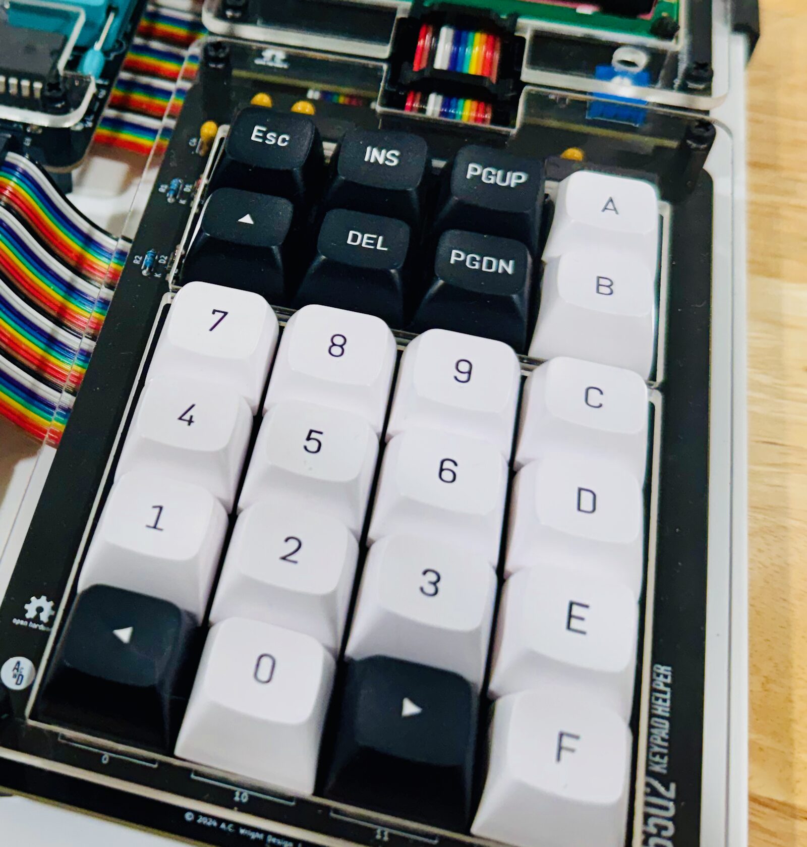
The pad as it sits
ESC | INS | PGUP | A |
▲ | DEL | PGDN | B |
7 | 8 | 9 | C |
4 | 5 | 6 | D |
1 | 2 | 3 | E |
◄ | 0 | ► | F |
Every code
The LCD column is the single character the monitor shows for that key while you are navigating.
| Code | PA4…PA0 | Key | On the LCD | Hex value |
|---|---|---|---|---|
$00 | 0 0 0 0 0 | ◄ | < | — |
$01 | 0 0 0 0 1 | 1 | 1 | 1 |
$02 | 0 0 0 1 0 | 2 | 2 | 2 |
$03 | 0 0 0 1 1 | 3 | 3 | 3 |
$04 | 0 0 1 0 0 | 4 | 4 | 4 |
$05 | 0 0 1 0 1 | 5 | 5 | 5 |
$06 | 0 0 1 1 0 | 6 | 6 | 6 |
$07 | 0 0 1 1 1 | 7 | 7 | 7 |
$08 | 0 1 0 0 0 | 8 | 8 | 8 |
$09 | 0 1 0 0 1 | 9 | 9 | 9 |
$0A | 0 1 0 1 0 | 0 | 0 | 0 |
$0B | 0 1 0 1 1 | ► | > | — |
$0C | 0 1 1 0 0 | F | F | 15 |
$0D | 0 1 1 0 1 | E | E | 14 |
$0E | 0 1 1 1 0 | D | D | 13 |
$0F | 0 1 1 1 1 | C | C | 12 |
$10 | 1 0 0 0 0 | ESC | * | — |
$11 | 1 0 0 0 1 | INS | I | — |
$12 | 1 0 0 1 0 | PGUP | U | — |
$13 | 1 0 0 1 1 | A | A | 10 |
$14 | 1 0 1 0 0 | ▲ | ^ | — |
$15 | 1 0 1 0 1 | DEL | X | — |
$16 | 1 0 1 1 0 | PGDN | N | — |
$17 | 1 0 1 1 1 | B | B | 11 |
The code is not the value
They line up for 1 to 9 and nowhere else. Key 0 is code $0A, and C to F run backwards — $0C is F and $0F is C. The encoder numbers the switches in the order they sit on the board, and the firmware turns that into a digit with a lookup table.
If you read a code off the port yourself, you must look it up. There is no arithmetic that gets you there.
How a press arrives
The encoder raises its data-available line into the PIA's CA1, which fires an interrupt. The handler reads the code off PA0–PA4 and CA2 drops the encoder's output enable again.
So the monitor never sits in a polling loop and never misses a keystroke, even while it is running your program. That is also how ESC can stop something that has no intention of stopping.
The same PIA drives the display: Port A's top three lines are the LCD's RS, R/W and E, and Port B is its data bus. One chip, two jobs.
📄 Keypad Mapping card — the pad and all twenty-four codes on one printable page.